GUIDELINES FOR THE DESIGN
Follow all the steps to prepare your file step by step. On this page you will find everything you need (measurements and techniques) to present your document correctly and make the design phase easy and intuitive.
FILE PREPARATION
Tesseletion
Before 3D printing It is necessary to perform tessellation of the model. We mean that it is necessary to convert the geometry of the model into triangles. The standard format is STL (BINARY or ASCII).
The recommended values for distance and angle are 0.05 and 1.
Do the export in mm.
MAXIMUM PRINTABLE AREA
The maximum print volume is X 380mm - Y 284mm - Z 380mm.
DIMENSIONAL PRECISION
The dimensional precision obtainable is between ± 0.3 mm up to 100 mm and 0.3% above that value.
MINIMUM TECHNICAL SPECIFICATIONS OF THE PARTIES
Minimum printing characteristics
The minimum printing characteristics in the X, Y and Z planes are as follows:
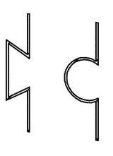
- With a top thickness of 1 mm the minimum slot is 0.5 mm.
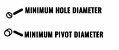
- The diameter of the minimum hole with thickness = 1 mm is 0.5 mm.
- The diameter of the minimum axis with a height of 10 mm is 0.5 mm
- Blind holes or holes with a tiny diameter may get clogged with dust
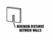
- The minimum gap between walls is 0.5 mm.
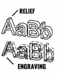
Engraving
Multi Jet Fusion technology allows you to print letters and drawings with high resolution and definition.
Any text, number or design included in a part is recommended to be at least 1 mm in depth or height.
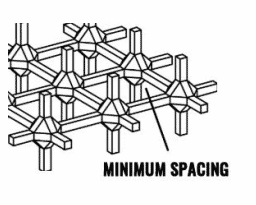
Solid part or structural filling
Multi Jet Fusion allows you to print the optimized topology or even small lattice structures. This type of design helps to reduce the weight of the part and the amount of material used.
The minimum recommended spacing in a reticular structure to ensure that all the material inside can be removed is 1 mm.
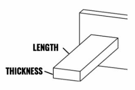
Wall thickness
The minimum thickness that can be printed depends on the proportion between the length and thickness of the wall:
Aspect ratio = length / thickness
- With a wall thickness of less than 1 mm, Aspect ratio should be less than 1. There are no specific recommendations for thicknesses greater than 1 mm.
- For parts with a high Aspect ratio, it is recommended to increase the wall thickness or add protusions to reinforce the part.
- Very thick walls can accumulate heat and cause spot constrictions.
- Walls with a thickness above 10mm are not recommended since small cavities may form on the surface
In general, the recommended minimum wall thickness is 1mm.
Minimum distance between parts to be assembled
When two parts must be assembled together it is recommended to leave a gap in the interference areas of at least 0.4 mm (± 0.2 mm tolerance in each part).
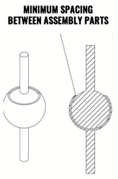
Minimum spacing between printed parts as assemblies
Assembly parts printed together must have a minimum distance of 0.7 mm. Parts with very thick walls above 50 mm should have more space to ensure adequate performance.
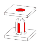
Large parts
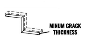
Large parts can be sectioned and reassembled after printing by joining them with glues or with joining pivots.
If you plan to glue the parts together we recommend interlocking them with a profile as shown in the figure.
In addition to the minimum spacing between the parts to be assembled (see previous paragraph), an additional space of 0.1-0.2mm must be left between the walls for the glue.